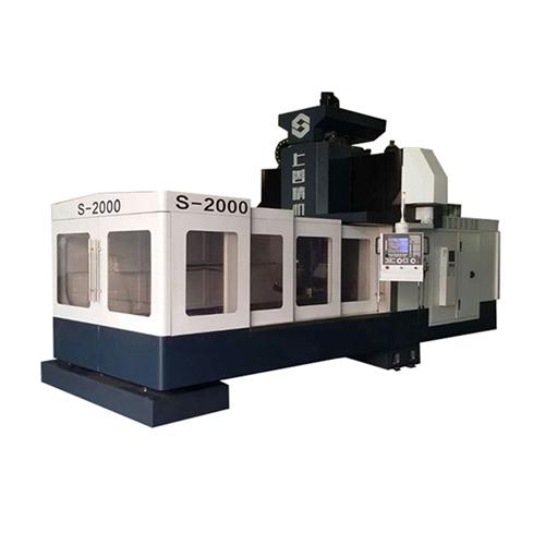
(1) The adjustment of CNC machine tool / system parameters is mainly adjusted according to the machine tool performance and characteristics.
Movement speed and feed parameters of each feed axis.
Adjust the integral constant of each feed axis.
Adjusted the control parameters of the spindle.
Parameter adjustment of tool changer.
Parameter adjustment of other auxiliary devices. For example: hydraulic system, pneumatic system
 (2) Spindle function
 1 Manual operation selects low, medium and high three-level rotation, the spindle performs five forward and reverse start and stop, check its flexibility and reliability, and check that the power display on the load meter meets the requirements.
The manual data input mode (mdi) enables the spindle to start at a low speed and gradually increases to the maximum speed allowed. Check whether the rotation speed is normal, and the general allowable error should not exceed 10% of the soil speed indicated by the machine tool. At the same time, check whether the spindle speed is normal, whether the spindle noise, vibration, and temperature rise are normal. The total noise of the machine tool should not exceed 80 decibels.
Check the flexibility and reliability of the spindle more than five times.
(3) Check of each feed shaft. The low, medium and high feed and fast movement of each feed shaft operated manually are correct movement ratio, smooth, smooth and no noise during movement.
(2) Manual data input (mdi) can detect the rapid movement and speed of each data given by g00 and g01f.
(4) The inspection of the replacement tool should check whether the replacement tool is flexible and sturdy during manual and automatic tool replacement.
Manually check whether the tool changer is flexible and strong.
Automatic operation, check whether the tool changer is flexible and strong during the tool change process.
(5) Limited position, mechanical zero point inspection to check the reliability of the machining center's soft and hard limits. The soft limit is generally determined by the system parameters; the hard limit is determined by the travel switch, generally at the limit position of each feed axis.
The method to check the accuracy and reliability of each feed axis to return to the origin is zero return.
(6) Check that other auxiliary devices such as lubrication system, hydraulic system, pneumatic system, cooling system, lighting circuit, etc. are working properly.
================================================== ================================================== ======
1. Description
Naipu G series Gravel and sand slurry pump is
designed specifically for continuous pumping of extremely aggressive
slurries, with a wide particle size distribution. Capable of handling
large particles at consistently high efficiencies results in low cost of
ownership. The large volume internal profile of the casing reduces
associated velocities further increasing component life.
Typical Applications---
Slag Granulation
Suction Hopper Dredging
Dredging
Barge Loading
Sand Reclamation
Sugar Beet
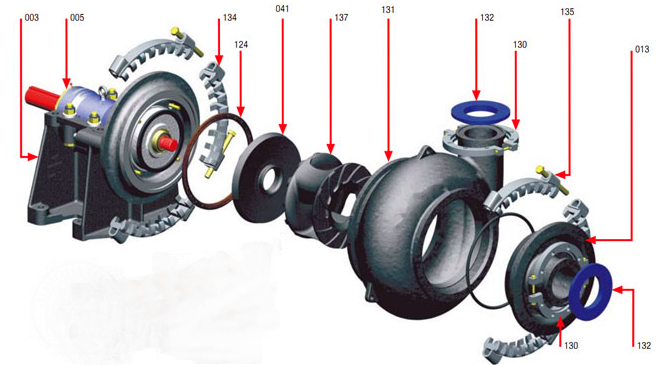
2. G series gravel and sand slurry pump construction drawing

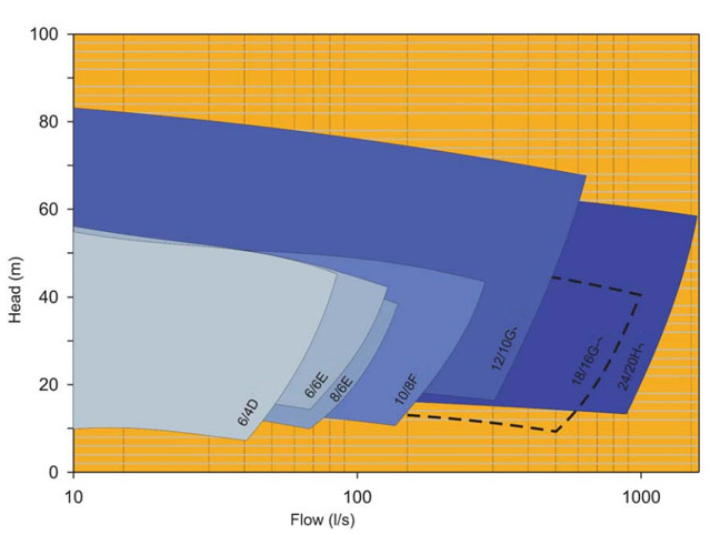
3. G series gravel and sand slurry pump select chart

4. G series gravel and sand slurry pump performance parameters

River Sand Pump,Horizontal Gravel Pump,Sand Dredging Pump,Gravel Sand Slurry Pumps
Shijiazhuang Naipu Pump Co., Ltd. , https://www.naipu-pump.com