Abstract: According to the change of the die edge size after wear, the wear type of the die edge size is recognized, and the edge size is automatically calculated. With AutoCAD as the platform, VC++6.0 and CAD development tool ObjectARX are used according to the programming principle of 3B instruction. The entity is processed and the 3B program and the molybdenum wire center track are automatically generated.
The main parts of the blanking die are completed by wire cutting [1], but the type of dimensional change after the edge of the die is not automatically judged [2~4], and the result of manual input must be judged, and the efficiency is not high. Aiming at this situation, this paper proposes a fast and efficient automatic calculation method of the edge size. According to the characteristics of the blanking piece and the inner ring, the extracted information is calculated and the calculated figure is calculated. The information is extracted and processed, and the interface software developed by VC+ + and ObjectARX is used to automatically convert the AutoCAD graphics of the machined parts to the line cutting 3B instruction code [5~7], thus effectively improving the operating efficiency of the CAD/CA M system. [8].
First, the die edge size calculation
The size of the blanking member depends on the lateral dimension of the bright strip. The size of the blanking member depends on the size of the die edge, and the size of the punching member depends on the size of the punching edge. In the programming calculation, since the parts are matched with each other, it is only necessary to determine the cutting edge size of one part, and then process other parts by different compensation amounts.
1. The calculation principle of the die edge size is based on the knowledge of punching die design and manufacturing. The die cutting edge size must follow several principles: 1 According to the characteristics of blanking and punching, the size of the blanking piece depends on the die size. Therefore, the blanking die should first determine the size of the die, and reduce the size of the punch to ensure a reasonable gap; the size of the punching member depends on the size of the punch, and the punching die should first determine the punch, by increasing the die size. Ensure a reasonable gap. 2 According to the wear law of the cutting edge, if the edge size becomes larger after wear, the basic size of the cutting edge should be close to or equal to the minimum limit size of the workpiece; if the cutting edge size becomes smaller after wear, the basic size of the cutting edge should be close. Or equal to the maximum limit size of the workpiece. The manufacturing precision of 3 convex and concave molds is generally 2 to 3 higher than the accuracy of the workpiece, and the tolerance is “one-way into the bodyâ€, that is, the tolerance of the shaft size (the size of the contained surface) is negative (ie, L0-δ); The tolerance of the hole size (including surface size) takes a positive value (ie, L+δ0); the non-porous non-axis size takes a symmetric distribution tolerance (ie, L±δ/2).
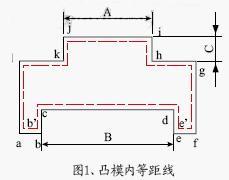
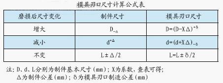
2, determine the blade size wear type and calculation formula convex and concave mold manufacturing has two methods: separate processing and processing. This method is generally used in factories because it is easy to ensure the gap due to the processing and the manufacturing tolerances of the mold can be enlarged. With the matching processing method, it is necessary to judge the type of wear of the blanking part, and select the corresponding calculation formula for calculation. There are three variations in the size of the die edge after wear: decrease, increase or not change. To automatically determine the type of wear of the die edge size, it is necessary to analyze the blank geometry. In the blanking die, the blanking size is generally based on the die, the punching size is based on the punching die, and the die is expanded outward after the die is worn, and the punch is inwardly reduced after being worn, and the die is calculated. From the line and the equidistant line in the punch, the offset geometry can be obtained. The dashed line shown in Figure 1 is the drawn equidistant line within the punch.

By comparing the dimensional changes before and after wear, the type of wear for each size can be automatically determined. As shown in Figure 1, the A dimension decreases, the B rule increases, and the C dimension does not change. Depending on the position of the size, on the outer ring or on the inner ring, and the type of wear, the calculation formula can be selected (see the mold edge size calculation formula table).

Next page
Metal Door Skin,Metal Door Skin Design,Metal Skin Door,Door Skin Sheet
Xiamen XMillion Co.,Ltd. , https://www.xmilliondoor.com