Overview
SUNYUAN SY series AD products (Adam module) can realize signal safety isolation and high-precision data acquisition, isolation conversion, monitoring and transmission between sensor and host. The data acquisition result is displayed in two modes through the LED digital tube, and the display result can be directly monitored according to the field data. Products are widely used in RS-232/485 bus industrial automation control system, 4-20mA / 0-10V signal measurement, monitoring and control, small signal measurement and industrial field signal isolation and long-distance transmission and other remote monitoring applications. Through the configuration of the software, a variety of sensor types can be connected, including current output type, voltage output type and the like.
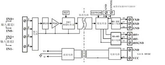
The product includes power isolation, signal isolation, linearization, A/D conversion and RS-485 serial communication. Each serial port can connect up to 256 SY AD series modules. The communication mode adopts ASCII character communication protocol or MODBUS RTU communication protocol. The instruction set is compatible with ADAM module. The baud rate can be set by the user and can be linked with other manufacturers' control modules. On the same RS-485 bus, it is convenient for host programming.
SY series AD products are intelligent monitoring and control systems based on single-chip microcomputer. All user-set calibration values, address, baud rate, data format, checksum status and other configuration information are stored in non-volatile memory EEPROM.
SY series AD products are designed and manufactured according to industry standards. The signal input/output is isolated, can withstand 3000VDC isolation voltage, strong anti-interference ability and high reliability. Operating temperature range - 45 ° C ~ +80 ° C.


Features
â— Low cost, small size modular design for desktop or rail installation â— Data acquisition isolation converted to RS485/232 support Modbus RTU communication protocol â— Measurement accuracy better than 0.05%, programmable calibration module accuracy â— Signal input / output isolation Withstand voltage 3000VDC
◠Wide power supply range: 8 – 50VDC
â— High reliability, easy programming, easy installation and wiring â— User programmable setting of target module address, baud rate, etc. â— Data acquisition results are displayed in LED digital tube in two modes â— Can be monitored directly based on field data acquisition and display results
typical application
â— Industrial equipment operation measurement, monitoring and remote control â— Intelligent building control, security engineering and other automation system monitoring â— RS232/485 bus industrial automation system remote monitoring â— Sensor signal isolation conversion and long-distance transmission â— Analog signal A/D conversion, adjustment and remote Transmission â— Acquisition and recording of industrial site multi-channel operation data â— Medical and industrial control product development â— Analog 4-20mA/0-10V signal acquisition isolation and transmission
Introduction to SYAD02/4B function
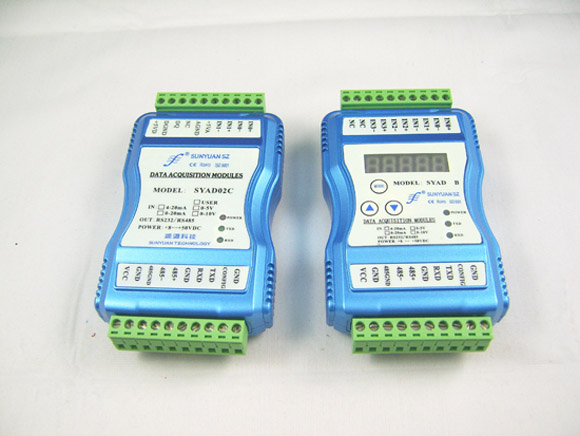
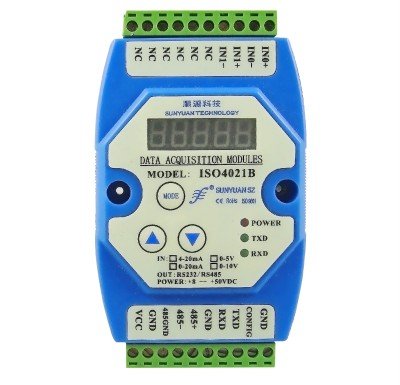
The SYAD02/4B signal isolation acquisition module can be used to measure a voltage or current signal. It can also be used to measure two or four channels of current or voltage signals that can be grounded together without interfering with each other. The data acquisition results are displayed in two modes through the LED digital tube.
The analog signal input is 24-bit acquisition accuracy, and all signal input ranges have been calibrated before leaving the factory. When in use, the user can also easily program and calibrate.
For the specific current or voltage input range, please refer to the product selection. When measuring two signals, the two input selections must be the same.
Selection example 1: Model: SY AD 02B-A4 means two channels, 4-20mA signal input.
Selection example 2: Model: SY AD 04B-A7 means four-channel, 0-±20mA signal input.
Selection example 3: Model: SY AD 02B-U1 means two channels, 0-5V signal input.
1. Communication protocol communication interface: 1 standard RS-485 communication interface and 1 standard RS-232 communication interface.
Communication Protocol: Supports two protocols, ASCII character protocol and MODBUS RTU communication protocol. The communication protocol can be programmed to enable network communication with various brands of PLC, RTU or computer monitoring systems.
Data format: 10 digits. 1 bit start bit, 8 data bits, 1 stop bit.
Communication address: (00H-FFH) and baud rate (300, 600, 1200, 2400, 4800, 9600, 19200, 38400bps) can be set; the communication network can be up to 1200 meters long, connected by twisted pair shielded cable . Communication interface with high anti-interference design, ±15KV ESD protection, communication response time less than 100mS.
2. Anti-interference can be set as required. The module has a transient suppression diode inside, which can effectively suppress various surge pulses, protect the module, internal digital filtering, and also can effectively suppress the power frequency interference from the power grid.
General parameters
(typical @ +25°C, Vs is 24VDC)
Input Type: Current Input / Voltage Input Accuracy: 0.05%
Input offset: ±0.1 uA/°C
Temperature drift: ±15 ppm/°C (±30 ppm/°C, max)
Input protection: Overvoltage protection, overcurrent protection input resistance: 50Ω (4-20mA/0-20mA/0-±20mA current input)
100Ω (0-10mA/0-±10mA current input)
1KΩ (0-1mA/0-±1mA current input)
Greater than 1MΩ (voltage input)
Bandwidth: -3 dB 10 Hz
Conversion rate: 10 Sps
Common Mode Rejection (CMR): 120 dB (1kΩ Source Imbalance @ 50/60 Hz)
Normal mode suppression (NMR): 60 dB (1kΩ Source Imbalance @ 50/60 Hz)
Communication: Protocol RS-485 or RS-232 ASCII character protocol and MODBUS RTU communication protocol baud rate (300, 600, 1200, 2400, 4800, 9600, 19200, 38400bps) software configuration address (00H~FFH) software Configure communication response time: 100 ms max
Working power supply: +8 — 50 VDC wide power supply range, internal anti-reverse and overvoltage protection circuit power consumption: less than 1W
Working temperature: - 45 — +80°C
Operating humidity: 10 – 90% (no condensation)
Storage temperature: - 55 — +85°C
Storage humidity: 10 - 95% (no condensation)
Isolation withstand voltage: between input / output: 3KVDC, 1 minute, leakage current 1mA
The output and the power supply are common to the ground.
Impact voltage: 3KVAC, 1.2/50us (peak)
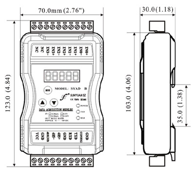
Dimensions: 123 x 70 x 30 (mm)

Initialize the SYAD02/4B module
When accessing the RS-232/RS-485 network, the SYAD02/4B module must be assigned a unique address code, the address code is a hexadecimal number, and the value is between 0x00 and 0xFF. All new SYAD02/4B modules use the same factory initial setup as follows:
The address code is 01H
Baud rate 9600 bps
Suppression checksum
ASCII character communication protocol
Since the address codes of the new modules are the same, their addresses will contradict other modules, so when you build the system, you must reconfigure the address of each module. After the SYAD02/4B module power cable and RS485 communication cable are connected, the configuration command can be used to modify the address of the SYAD02/4B module. The baud rate, checksum status, and communication protocol also need to be adjusted according to user requirements. Before modifying the baud rate, checksum status, and communication protocol, the module must first enter the configuration state, otherwise it cannot be modified.
How to get the module into the configuration state
The SYAD02/4B module has a special pin labeled CONFIG. Short-circuit the CONFIG pin to the ground (GND pin), then turn on the power, and the module enters the configuration state. In this state, the module is configured as follows:
Address code is 00H
Baud rate 9600 bps
Suppression checksum
ASCII character communication protocol At this time, you can modify the baud rate, checksum status and other parameters of the SYAD02/4B module through configuration commands. You can also select the communication protocol by setting the communication protocol command of the module. When you are not sure about the specific configuration of a module, you can also configure the jumper to make the module enter the configuration state and then reconfigure the module. If the user needs to set the module to the MODBUS RTU communication protocol, please see the MODBUS communication protocol chapter for instructions.
Module calibration
Calibration must be done under the ASCII character communication protocol. Calibration is not supported under the Modbus protocol.
The product is calibrated at the factory and can be used directly without calibration. The user can also recalibrate the module during use. When calibrating, the module needs to input the appropriate signal, and different input ranges require different input signals.
To improve calibration accuracy, the following equipment is recommended for calibration:
1. A DC voltage/current signal source with stable output and low noise
2. A 5-bit or higher-precision voltage/current measuring instrument monitors the accuracy of the input signal
Calibration process
1. Select the input channel to be calibrated and connect the corresponding input signal according to the input range of the module.
2. The SYAD02/4B module zero point is calibrated at input 0, and the full scale is calibrated at 120% of the input full scale. For example, when inputting 4-20 mA, input 0 mA when calibrating zero, and input 24 mA when calibrating full scale (0V input, 0V when calibrating zero, and 6V when calibrating full scale).
3. Input the zero signal to the channel that the analog input module needs to calibrate, usually 0mA or 0V.
4. After the signal is stable, send an offset calibration $AA1N command to the analog input module (N represents the channel code currently being calibrated, 0 or 1).
5. Input the current or voltage signal of 120% of full scale to the channel that the analog input module needs to calibrate.
6. After the signal is stable, send the gain calibration $AA0N command to the analog input module (N represents the channel code currently being calibrated, 0 or 1).
7. Calibration is complete
Instructions for the use of LED digital tube display
SYAD02/4B is an analog data acquisition module with display. The collected analog voltage or current value is displayed by a five-digit LED digital tube, which is convenient for the user to view the current collected value. If no display is required, the user can turn off the display with the MODE button. When the display is turned on, two display modes are used, namely single channel display and multi-channel cycle display.
The display data format is: channel number, symbol mark, four-bit data bit; data bits are divided into integer and fractional parts, separated by a decimal point. The first digit from the left is the channel number (1-4), and the channel number is followed by a decimal point for the symbol mark. The decimal light indicates that the current collected data is positive. If the decimal point is off, it means the current collected data is negative. The last four digits of data are the decimal values ​​of the acquired data.
Display mode
The mode is switched by the mode switch button (MODE button). When the mode button is pressed, the LED briefly displays C1 to indicate that the current mode is the single channel display mode, and the short display C2 indicates that the current mode is the multi-channel cyclic display mode.
C1: Single channel display. In this mode, the LED only displays the acquisition value of one channel at a time (the channel number indicates which channel data is displayed). The two channel switching buttons below the mode button switch the display channel. After the left button is pressed, , the channel number is incremented by one; when the right button is pressed, the channel number is decremented by one.
C2: Multi-channel cyclic display. In this mode, the LEDs display the collected values ​​of each channel at a fixed time interval. To switch the display mode or turn off the display, just press the mode button (MODE).
Detailed technical information:
Http://


The cap nut, as its name implies, is a hexagon nut with a cap. Its function is to fasten the exposed part on the outside to prevent moisture or other corrosive substances from entering the inside, thus playing a role in rust prevention, and thus improving the service life of the cap itself and the connector.
Cap Nut,Domed Cap Nut,Dome Nut,Brass Cap Nut
Jiangsu Jiajie Special Screw Co., Ltd , https://www.jiajiescrewcompany.com