Multi-wire cutting machine is a kind of high-efficiency cutting device which has developed very rapidly in recent years. It is widely used in the semiconductor industry. Many semiconductor single crystal materials are processed by multi-wire cutting machine. In recent years, ultra-thin solar wafer cutting A large number of multi-wire cutting machines are also used. It mainly uses a multi-turn metal wire to cut the material to be cut. Since the diameter of the metal steel wire is small, it is generally between 0.08mm and 0.16mm. After special machining of the shaft roller groove, it can grind the silicon wafer with a thickness of about 200um. The latest technology multi-wire saw can even cut ultra-thin silicon wafer with a thickness of 120um. Due to the small diameter of the cutting line, the cutting process is in progress. The loss of materials is also correspondingly reduced, and the cutting efficiency is high. The surface roughness, TTV value, curvature, and warpage of the cut silicon wafer are better than those of other methods, and the geometric parameters of the wafer are mainly Depending on the process conditions of the multi-wire cutting machine, multi-wire cutting machines are widely used in the cutting of semiconductors and solar wafers. As the technology matures, many lines are currently available. Cutting means cutting has become a major solar wafer cutting. The principle of multi-wire cutting machine cutting is as shown.
During the slow decline of the silicon rod material, the multi-turn metal steel wire wound in the shaft groove is subjected to high-speed one-way or reciprocating motion, and the mortar sprayed on the metal steel wire is continuously grinding the silicon material, thereby The silicon rod is cut into a plurality of silicon wafers. In the cutting process of the silicon rod, the role of the mortar is very important. The mortar must have sufficient cutting ability and maintain a certain density and viscosity. The mortar sprayed onto the cutting line must also have sufficient flow rate to cut. During the process, as the continuous relative motion between the cutting line, the mortar and the silicon material generates a large amount of heat, the mortar used as the cutting medium must take away the generated heat to maintain the normal operating temperature of the system, otherwise, the generated heat Accumulation will gradually increase, so that the temperature of mortar and silicon material will gradually increase, which will have a serious impact on the quality of silicon wafer cutting, prone to chipping, surface damage, defects, and even breaks. Therefore, in the silicon wafer cutting process, the density, flow rate, temperature and other data of the mortar should be monitored in real time according to the cutting state of the silicon material, and the mortar flow rate can be controlled in real time according to the monitoring data. Therefore, studying the mortar control system of the multi-wire cutting machine, obtaining a stable mortar flow rate is very important for the silicon wafer cutting process.
1 Mortar control system is based on the requirements of TTV value and surface roughness of solar wafer. When using multi-wire cutting machine to cut silicon rod, the fluctuation range of mortar flow rate is kept at 2L/min. If the mortar flow rate is too large, it will slice. The impact is formed, and the cutting process will cause the piece to fall off. The flow rate of the mortar is too small, which will result in insufficient cutting ability and high cutting temperature, thus affecting the surface quality of the silicon wafer. The temperature fluctuation range of the mortar is required to be kept within 1C during cutting, and the temperature fluctuation is too large. It is easy to affect the cutting state, and even cause wire breakage, which causes the cutting silicon rod to be scrapped. According to the system control requirements of mortar temperature and flow rate, the design of mortar control unit is composed of mass flow sensor, mortar pump, mortar mixing pump, mortar spraying device and motion controller. According to the control requirements of mortar flow, the system composition is as shown.
The agitating pump can stir the grinding sand and the cutting oil into a mortar slurry of a certain density to fully mix the sand and the cutting oil, and the mortar pump is used for extracting the evenly mixed mortar into the mortar injection pipe, and spraying to the cutting at a certain flow rate. On the line, for high-speed cutting of silicon rods, because the flow rate is very important for the cutting of silicon wafers, the mass flow sensor is set to monitor the mortar flow rate in real time, and the speed of the mortar pump is dynamically adjusted by the motion controller to make the mortar flow rate according to the set value. Variety.
2 mortar control method analysis and realization According to the system control requirements for mortar flow and temperature, using the easy-to-implement ON-OFF mode for control, first test the mortar flow control system, set the mortar flow rate, and set the flow fluctuation The range is -2L/min - 2L/min, the mortar flow rate rises from zero, and the flow rate sensor detects the change of mortar flow. If the flow rate fluctuation is greater than the set value +2L/min, the control system will reduce the speed of the mortar pump. Increase the mortar flow rate. If the flow rate fluctuation is less than the set value -2L/min, the control system will increase the mortar flow rate by increasing the speed of the mortar pump. It can be known from the test that the ON-OFF control method can not meet the requirements of control accuracy, and the PID control method is proposed to improve the control precision. The formula according to the output of the PID algorithm is as follows: integration time (Ti); D value is the derivative time (Td). The proportional PB control output is the basic factor for controlling the accuracy of the mortar flow, and e = PV (current value) - SV (set value). When the current mortar flow rate is equal to the set flow rate, the e value is zero. At this time, there is no output in the P control, and the P output is unable to keep the mortar flow at the set value all the time. At this time, the I control is required to perform the compensation action. Therefore, when the I quantity control is activated, the public 1/Til/PBedt is also calculated. It is known that Ti is located at the position of the denominator, so the smaller the Ti value is, the larger the integrated amount is calculated; otherwise, the larger the Ti value is. , the smaller the calculated amount of points. When the system mortar flow changes, the D amount control will be activated. In the system, when the mortar flow rate drops rapidly, U (output) = P amount + I amount + D amount. On the contrary, when the mortar flow rate in the system rises rapidly, U (output) = P amount + I amount - D amount, so the amount of D is used to control the rapid response of the output when the flow rate changes sharply to reduce and set the value. error. The D value is calculated by the public TD1/Pbde/dt calculation, so the higher the D value, the faster the reaction speed; conversely, the smaller the D value, the slower the reaction speed.
According to the PID control method, the mortar flow rate is controlled separately, the mortar flow rate and temperature are set, and the flow rate and temperature are monitored in real time. Because the mortar flow rate rises slowly, PID control can better control the change of mortar flow rate, but the mortar flow rate starts. Overshoot occurred in the control, and the detected flow data is as shown.
The analysis found that since the mortar flow rate rises slowly after starting, the monitoring flow rate is low, it is necessary to increase the speed of the mortar pump to increase the flow rate, and the increase of the rotation speed causes the flow rate to increase rapidly, thereby causing the flow rate to be too high, and forming an up and down oscillation. In fact, if the P value is adjusted too small, the flow rate will increase too much and cause up and down oscillation. If the P value is adjusted too much, the flow response speed is slow and it is difficult to reach the set flow value. Value and D value adjustment. By repeatedly adjusting the PID parameters, the fluctuation of the mortar flow rate can be well controlled within 2 L/min, and the flow rate is also very constant during long-term operation.
3 Flow control method verification and discussion Using the adjusted PID parameters to control the mortar system for the cutting test of two single crystal materials, since the solar laurel bar material is quasi-square, the four corners of the cut silicon wafer are arc-shaped, and the actual cutting test is passed. It is found that the constant mortar flow rate is not suitable for the cutting of the silicon wafer, especially when the end is cut, the silicon wafer is easily washed away by the mortar, the cutting rate is reduced, the silicon wafer is seriously damaged, and the shape of the solar single crystal silicon wafer is accurate. Square, thickness between 180-200um, as shown.
The quasi-square shape of the silicon wafer is cut by a round silicon rod and ground and then ground. The formed quasi-square silicon rod is bonded to the glass holder during cutting, and when cut to the end of the silicon rod, silicon The contour of the sheet becomes smaller, the mortar impacts on the inclined surface of the silicon wafer, and the flow velocity will cause a great impact on the silicon wafer, causing some of the silicon wafer to fall and be damaged, and the mortar flow rate must be adjusted in real time according to the shape change of the silicon wafer. Therefore, the control method of changing the flow rate of mortar should solve this problem, that is, the mortar flow rate is adjusted in real time according to the change of the outer shape of the silicon wafer, so that the flow rate of the mortar is relatively constant, and changes with the shape of the silicon wafer. In addition, the cutting speed has a great influence on the chip collapse pit, and the variable speed feed control must be performed. By controlling the change of the feed speed of the silicon rod and the change of the mortar flow rate, the impact of the mortar at the cutting end is reduced, and the surface of the silicon wafer is increased. Quality and reduce chipping and breakage. For the 125mm specification silicon wafer, Ll=L2=125mm, hl=h2=20mm in the above figure, since the diameter of the circular arc part is 150mm, when the L1 changes to L0, the arc part changes little, and the mortar is on this. The effect of partial variation is small, and this part of the arc change can be regarded as a straight line. It is assumed that the speed of the silicon rod is V0 at L0 and the speed is V1 when feeding to L1. The length L of the part is changed as follows: B = B + 2 + 2 x A, and the over-transformation can be obtained: the meter is tested with a silicon wafer of 125 mm size, and the initial width L0 of the silicon wafer is detected to be 85 mm.
4 Conclusions This paper introduces the control method and control scheme of the mortar flow in the silicon wafer cutting by the multi-line cutting machine through test analysis, and terminates the failure by returning to the invalid Bob if the certification of A is turned down on page 231. Otherwise she sends it to Alice, where 2AV2 = H(eid)r(M) signature, Bob can be generated with the known r2. Take the above SPK as SPK4. If the authentication of n4 returns invalid, Alice also terminates with this failure. Otherwise she calculates tag1=i1, i2, and terminates.
The connection verifies the input tags tag1, tag2, and if they are equal, the algorithm returns to connect, otherwise it tells that it is not connected.
4 Conclusions The Peer-to-Peer Anonymous Authentication (PPAA) proposed in this paper better balances the peers' network privacy protection and corresponding accountability, so that the nodes in this non-central network also have a two-way peer identity. And provide higher security and better operational efficiency.
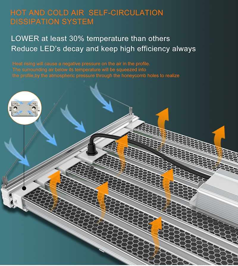
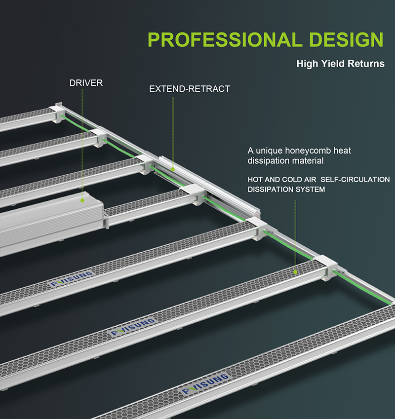
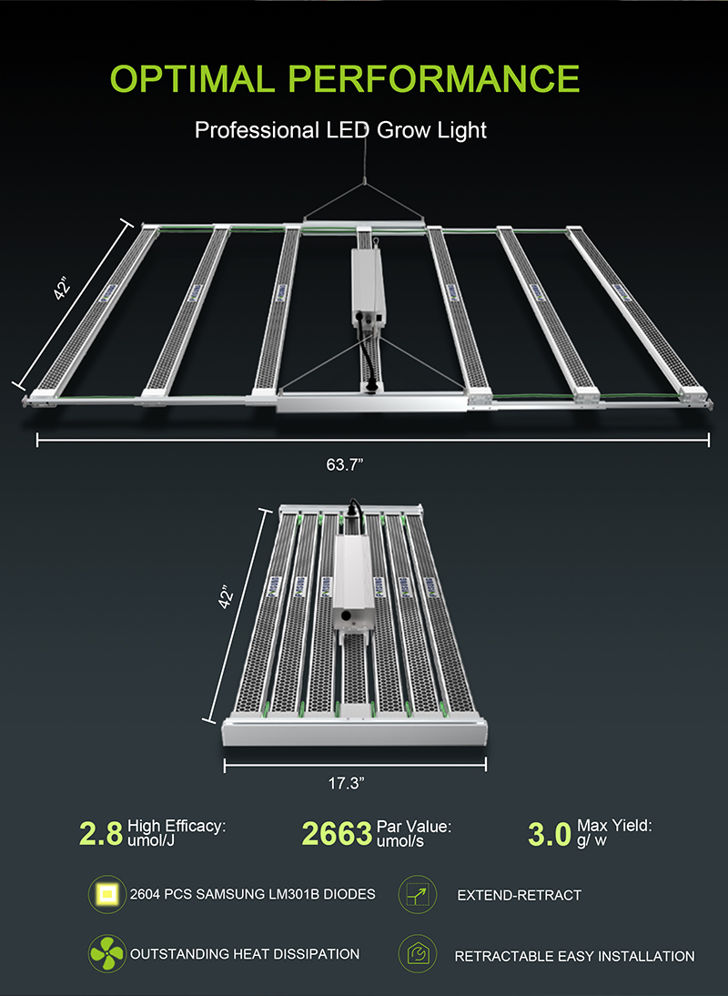
The 1000W adjustable plant light is a versatile and efficient lighting solution for indoor gardening. With its adjustable design, it allows users to customize the light intensity and coverage area to meet the specific needs of their plants at different growth stages. The 1000W power output ensures ample brightness for optimal photosynthesis, promoting healthy and vigorous plant growth. Equipped with advanced cooling technology, it effectively dissipates heat, preventing damage to the plants and extending the lifespan of the light. This reliable and energy-efficient plant light is a must-have for any indoor gardener looking to maximize their plant's potential.
This plant light is mainly used for indoor planting and provides the required light for the plants. It can simulate the spectrum of sunlight, including blue, red and white light, to meet the needs of plants at different growth stages.
1000W plant lamps have high light intensity and coverage, which can cover a large planting area. It can provide enough light to promote photosynthesis and growth of plants.


lighting full spectrum grow for veg and flower,indoor grow lights,led white light grow light
Shenzhen Pvison Technology Co., Ltd. , https://www.pvisunggrowlight.com