Abstract: This paper introduces a method of computer simulation of CNC turning process. Windows software was developed using object-oriented technology. The simulation software not only has strong practicability, but also has obvious advancement. In this paper, the dynamic simulation of tool path and the dynamic simulation technology of machining process are introduced in detail. Software operation proves its validity and correctness.
Machining simulation of NC programs is an important aspect in the field of simulation and an important part of computer integrated manufacturing systems. The traditional method of verifying the correctness of the NC program is to test it with a wooden mold, a wax mold or a plastic mold. In the computer environment, it is a new method to use the numerical control simulation method to verify the correctness of the NC program. By simulating the machining process of the part, it is possible to check the correctness of the NC code, and also to check whether there is interference (including collision and overcutting) between the tool and the workpiece, the machine tool and the fixture during the machining process. The machining process simulation can more realistically reflect the actual machining process. Errors found during the simulation can be corrected immediately. This method of verifying the numerical control code by performing the actual trial cutting of the numerical control lathe has the characteristics of being fast, intuitive, and time-saving. It saves manpower and material resources, improves production efficiency, guarantees processing quality, and adapts to the requirements of modern market for product development and manufacturing. Previously there was software developed and run under DOS. With the advent of object-oriented technology and VC++ development systems, it is of great significance to develop more convenient WINDOWS software that is more conducive to integration into CAD/CAM systems.
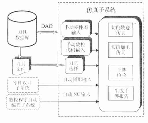
1 NC turning simulation system structure and processes <br> <br> NC program machining simulation system is an important component of integrated CAD / CAM system, which is based on turning simulation software tool database. The dynamic simulation subsystem is the core of the entire system, and simulation is the goal of the system. The simulation includes the completion of tool path simulation, the cutting simulation of material removal, and the interference (overcut and collision) between the tool and the part being machined. For CNC turning, the machining simulation system has to complete the following tasks: tool path simulation, machining simulation, interference checking and submission of simulation reports. The tool database is another important part of the system. It is the logistics support for the simulation system. It accommodates a large amount of tool data and is managed efficiently. Tool data management includes data entry, deletion, browsing, and searching. The system model is shown in Figure 1.
The machining of the parts by the turning tool mainly involves the processing of cylindrical surfaces, conical surfaces, spherical surfaces, threads, end faces, slots, cuts and the like. No matter what kind of parts are machined, the workpiece is made into a rotary motion (ie, the main motion): the cutter performs the motion of a straight line, an arc or other trajectory (ie, the feed motion). These movements can be done in simple CNC machining programs with simple commands such as G01, G02, G03. Since the simulation system is a simulation of the NC program in the PC, in order to be able to dynamically display the motion path or the cutting process of the tool on the screen of the PC in the simulation, the NC program instructions must be translated. Complete the syntax analysis, coordinate conversion and other work of the NC program, the process is as follows:
The simulation process processes the NC program to make it an NC coordinate information file. This file is the result of parsing and coordinate transformation of the NC program. The NC program is automatically generated by the CAD/CAPP/CAM integrated system or manually entered.
First, the NC coordinate file interpretation program reads the tool information from the NC coordinate information file and reads the corresponding tool information from the tool library file. Second, the NC coordinate file interpretation program reads the tool motion command and coordinate information from the NC coordinate information file, and calls the corresponding machining simulation algorithm to complete the tool trajectory simulation, cutting simulation and interference check.
Generate a simulation report and submit it to the CNC machine operator for analysis.

Figure 1 Database-based turning simulation system model
Next page
Gas Fireplace,Indoor Gas Fireplace,Natural Gas Fireplace,Gas Insert Fireplace
JINAN LODOR CNC EQUIPMENT CO.,LTD , https://www.zgfireplace.com