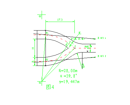
At that time, the design representative provided the graphical size relationship as shown, as well as the C-point geodetic coordinates and the large local angles of the outer sections, and some structural relationships within the tailgates. If the previous experience and instrument conditions are needed, it is necessary to establish a circular equation and solve the binary quadratic equation to find the geodetic coordinates of the arc corresponding to the center of the circle, and then the following calculations can be performed and the instrument can be considered for the lofting method. However, when we put this problem on the AutoCAD software platform, it becomes very simple. The specific operations are as follows:
First, on the AutoCAD software platform, the C point is entered according to the C point geodetic coordinates, and the hole axis of the C point is drawn according to the azimuth angle of the straight hole axis of the C point and its length, according to the dimensional relationship provided by the generation. P 1 , P 2 points, then use AutoCAD to draw the arc, so that it passes P 1 , C and P 2 , C point respectively, so that it satisfies R=28.00 m and conforms to the graphic direction. AutoCAD reuse annotation function, respectively, of the center of the two arcs labeled O 1, O 2 points, using the AutoCAD ID command can be O 1, O geodetic coordinates of the two points. Connect them to P 1 and P 2 with straight segments. Regardless of the direction of the cavern, and then were over P 1, P 2 as the point P 1 O 1, P 2 O 2 was perpendicular P 1 X 1, P 2 X 2, AutoCAD using convenient coordinate system setting function, are established to P1 point and P2 point are the coordinate system origin, P 1 X 1 and P 2 X 2 are the X-axis measurement construction coordinate system and then the coordinate system is moved to (0, -N) and named separately. At this point, our two auxiliary construction coordinate systems are established. These two coordinate systems ensure that the X axis is tangent to the arc of P 1 (or P 2 ) (this will be very beneficial to our next step.) Station and programming calculator application). By inputting the geodetic coordinates of the measured control points into the graph, the corresponding construction coordinates and construction coordinate azimuth angles of the control points can be obtained directly.
Fourth, the application of total station and programming calculator in the field
The total station we are currently using is the Swiss Leica 605L Total Station, which itself has the ability to work with coordinates. For the lofting of some three-dimensional coordinates in our actual work, we can use AutoCAD to build a digital model. First, use the programming calculator to perform simulation test on the computer AutoCAD platform. After the inspection procedure is correct, it can be used for the field lofting. For the open-air point line, we can directly use the coordinate lofting function of the total station, input the construction coordinates of the required stakeout point into the total station, and correctly obtain the correct desired point. The focus of the discussion now is on point lofting in some special cases in underground engineering. For example: the red line of the excavation of the underground powerhouse and the stakeout of the relevant structural points, the red line of the excavation of the underground cavern, and especially the excavation red line of the underground turning section and the stakeout of some related structural points. For the underground powerhouse, the top arch span is large, the main building is 24.36m, and the radius of the top arch is also 17m. During the construction process, the owners, supervisors, generations and construction parties all made clear requirements. It is necessary to strictly control over-excavation and prohibit under-excavation. This puts higher requirements on our surveyors from the stakeout method. After our repeated comparisons, we finally decided to use the total station instrument combined with the programming calculator to measure the three-dimensional construction coordinates on the spot, and then carry out the relevant calculations, thus releasing the required red line points. It turns out that our method is appropriate. Reasonable, the effect achieved is also ideal. The following is divided into two aspects to illustrate.
1. Calculation without plane turning:
As shown in Figure 5, the specific programming ideas are as follows:
First, we establish the center line of the B 1 B 2 unit as the E direction, and the direction of the vertical B 1 B 2 direction to the downstream direction is N direction, and establish the construction coordinate system with the origin of the B 1 point coordinate.

It is assumed that we need to open the red line of the top arch. The P coordinate of the measured point is (E, N, H), then the geometric relationship can be used to calculate the design H coordinate of the corresponding N coordinate or the design N coordinate of the corresponding H coordinate. This produces an H coordinate difference ΔH or N coordinate difference ΔN with our measured coordinates. then
ΔH 1 =2036.368-17.00+√(17.00 2 -(N+1.55) 2 )-H
ΔL 2 = 17.00-√((N+1.55) 2 +(H-2019.368) 2 )
ΔH 3 =2035.368-(15.36-√(15.36 2 +(N+1.55) 2 ))-H
ΔL 4 = 15.36-√((N+1.55) 2 +(H-2020.008) 2 )
ΔN=T×(N+1.55-T×√(17.00 2 -(17.0-(2036.68-H)) 2 ))
Previous page next page
Led Strip Lights,Led Phyto Lamp Strip Light,Led Plant Grow Strip Lights,Led Light Strips Non-Waterproof
Shenzhen You&My Electronic Technology Co., Ltd , https://www.szyoumyled.com