Measurement requirements
On-site measurement of machined products is the basic means to ensure the quality of machining. However, limited by the measuring methods and measuring tools, the on-site measurement of our machined products is limited to the measurement and control of the product size processing accuracy, but the processing accuracy of the shape and position of the important elements that form the product quality can not be done on site. measuring. At present, the accuracy of shape and position mainly depends on the model, the first piece is sent to the testing center for measurement, the precision of the machine tool is guaranteed, and a small number of special inspection tools are used to control. But these are often limited to dedicated, individual and qualitative measurement analysis, and it is impossible to replace effective 3D measurements. To solve the blind spot problem of on-site shape position tolerance measurement of high-precision processed products (such as camshafts, connecting Rods, cylinder heads, hoop boxes and hollow bushings, etc.), what is most needed is a field-friendly test. Tools, and meet the following requirements: 1 measurement accuracy can basically meet the design requirements and process testing requirements of most of our products. 2 easy to use. 3 data processing is fast. 4 It is possible to quickly establish an instantaneous three-coordinate measurement reference, which can easily perform various measurements on any part, assembly, fixture, and inspection tool that need to be used for relative position measurement.
2. Application research of detection methods
In the production site, the position and shape tolerance measurement of the product is completed. In addition to the current method of using the model and the special inspection tool on the individual parts, it is generally possible to install the heel detection device on the machine tool and the fixed coordinate measurement on the production site. Machine or measuring the marking machine and other means. These methods have been successfully applied in many domestic manufacturers, especially for online testing of the quality of large-scale specialized production lines.
For the machining production site of our company, from the current situation, there are several ways to use the three-coordinate measurement:
(1) On-line detection device. Such as the Marpos online detection device, the detection is convenient, the detection effect is real and reliable, because the price is more expensive, the equipment has not been equipped with the processing equipment added and modified for many years, and the future can be properly considered when adding new numerical control equipment. Install such detection devices to improve the quality and reliability of the machined products. However, the machine inspection can only meet the online measurement of individual equipment. Therefore, it is unrealistic to install a special inspection device with a certain precision level on the existing equipment.
(2) Install a fixed coordinate measuring machine on site. The use of such means is relatively common, but it also has certain limitations, mainly due to large floor space and high requirements for the environment, and most of the measuring machines generally placed at the production site are production type, measurement accuracy. Not high, the price is not cheap, it is not convenient to use.
(3) Use a portable coordinate measuring device. This is also a kind of on-site three-dimensional measurement method which has gradually emerged in recent years. Most of them are used for the accuracy of the relative position of the assembly production site. It is also used for the measurement of the fixture mold, as well as the measurement of various complex shapes. It is directly used for machining production. There seems to be not much on the scene.
Among the above three methods, the superiority of the portable three-coordinate measuring device is outstanding, and its advantages are reflected in:
First, it is easy to use. The measuring arm is light in weight, convenient to carry and easy to assemble. It can be installed in a variety of ways. The mounting surface can be freely selected on the ground, platform, product surface and machine surface as needed. The mounting table or mounting bracket can be freely installed without adjustment. Horizontal installation or even flip-chip will not affect the measurement accuracy; calibration when replacing the probe has convenient and quick on-site calibration.
Second, data processing is fast. It can easily complete the measurement and scanning of geometric elements, three-dimensional coordinates, geometrical tolerances and curves and surfaces, statistical analysis of a large number of measurement data, and give a graphical analysis report, which is intuitive and clear; the measuring arm can directly control the computer; with USB Data interface for hot swapping.
Thirdly, it is possible to quickly establish an instantaneous three-coordinate measurement reference, and it is convenient to perform various measurements on any occasion, such as parts, assemblies, fixtures, and inspection tools that need to be used for relative position measurement.
These advantages are essential for the on-line 3D inspection of multiple products at the production site.
At present, the manufacturers of portable coordinate measuring machines are mainly foreign manufacturers, such as the United States, such as France, Kexing and other companies. For the convenience of research, the FAROARM portable three-coordinate measuring arm recommended by the International Trade (Shanghai) Co., Ltd. is selected as the key research object, and the medium-precision titanium series measuring the radius of 1.2m is specified. This device basically has the main advantages of a portable coordinate measuring device. The applicability and reliability research is carried out by on-site physical measurement data acquisition and comparison with the company's existing high-precision coordinate measuring machine.
3. Suitability verification of portable coordinate measuring machine
Tables 1 to 3 show the data acquisition results for the 280 link, DF8B axle box and DF11 hollow bushing, respectively, using the FAROARM portable three-coordinate measuring arm and our company Zeiss CMM. .
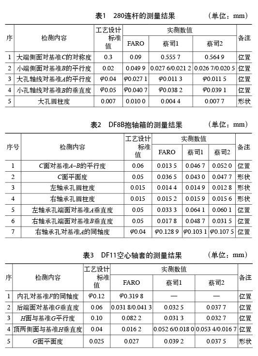
A total of 20 sets of data were collected for the three parts, of which 7 were shape tolerances and 13 were positional tolerances. The two types of data are separately compared, and the difference between the FARO data and the Zeiss data is < 1/3 of the tolerance band. The difference < 2 of the tolerance band is basically the same, and the difference > 2/3 is not consistent. According to this determination method, two types of data are compared and analyzed. The data of the shape tolerance group and the position tolerance group are shown in Tables 4 and 5, respectively. Among the “judgment resultsâ€, “1†indicates an agreement, “2†indicates a basic match, and “3†indicates a basic mismatch.
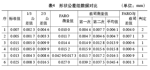
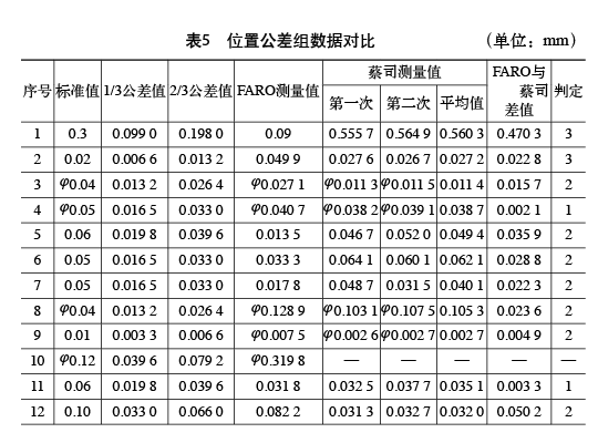
(1) Data analysis. Among the 7 groups of data in the shape group, 5 were consistent, 1 was basically consistent, and 1 was basically inconsistent. The data of anastomosis and basic anastomosis accounted for 85.7%. Among the 13 groups of data in the location group, there are 3 items that are consistent, 7 items are basically consistent, and 2 items are basically inconsistent, and one item is incomparable. The data of anastomosis and basic anastomosis accounted for 83.3%.
(2) Further analysis of data that is not consistent. A set of mismatched data of the shape group is the cylindricity of the connecting rod small hole. The standard tolerance value is very high, only 0.005mm, and any random factor may cause the deviation to exceed the limit.
The positionality has two sets of data which are basically inconsistent, which are the symmetry of the large end side of the connecting rod to the reference C and the parallelism of the small end side to the reference B. These two sets of data are related to the establishment and selection of the benchmarks, so different measurement methods may have differences in the selection of the benchmarks, resulting in large errors. For example, the symmetry of the large end side of the connecting rod to the reference C, and the selection of the reference C, the FARO uses a common midline reference formed by the two major end sides and the two small end sides, so the measurement result is very satisfactory, the rod used by Zeiss The midline baseline, so the measurement results vary greatly. Similarly, the parallelism of the small end side of the connecting rod to the reference B, if different measuring devices are used, the B-references are respectively selected with different large-end sides, which may also cause relatively large deviation, and the standard tolerance value is also small, so it is easy There is a mismatch.
(3) Preliminary conclusions on applicability. According to the above analysis, FARO is basically applicable to products, but for design values ​​with high precision requirements, data processing should be more cautious.
4. Reliability verification of portable coordinate measuring machine
Reliability verification is mainly to test the repeated measurement accuracy of the portable coordinate measuring device.
(1) Using FAROARM to continuously measure the four points determined on the wall of the 280-link large hole, collect a set of data and perform data processing as shown in Table 6. The average absolute difference = 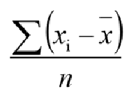 , range = xmax-xmin, variance
 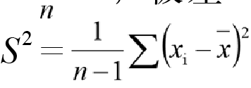 , standard deviation =
  .
.
According to the calculated values ​​in Table 6, it can be concluded that the standard deviation of the diameter of the measurement is S1=0.002 6 mm, and the standard deviation of the roundness is S2=0.001 5 mm. From this it can be concluded that the repeatability of the portable coordinate measuring machine is reliable.

(2) A company adopts a FARO portable coordinate measuring machine purchased in 2002 to measure at any measuring point on the standard block. The obtained sets of repeated measurement data and data processing results are shown in Table 7.
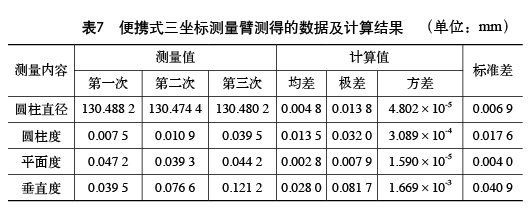
As can be seen from Table 7, the reliability of the accuracy between several sets of data varies greatly. According to the analysis, the first is that a company purchased a titanium 10-axis measuring arm with a 1.8m wingspan. The design accuracy level is lower than the titanium 6-axis measuring arm of the 1.2m boom that is currently demonstrated by our company. Second, the equipment model of a company is relatively early, and the time used is relatively long. Before the test, there is no requirement for the device to perform the accuracy verification, and the data collected are very random.
However, even so, the standard deviation of the diameter measurement and the standard deviation of the flatness still show a high consistency of <0.01 mm.
(3) Preliminary conclusions on reliability. From the data in Tables 6 and 7, and the actual field test conditions, the data measured on-site by the portable coordinate measuring machine is basically reliable, but the accuracy is required to be measured periodically. In fact, any gage used in the field needs to be regularly checked for accuracy and reliability.
5 Conclusion
The products of our company's machining are mainly Harmony Type 5 diesel locomotive (HXN5) and 280 diesel engine series rail transit parts. There are many medium-sized parts with a length of about 1m, all of which have higher precision requirements for shape and position tolerance control. . Typical components such as connecting rods, cylinder heads, camshafts, axle boxes, hollow shafts, and various gearboxes. The length tolerance values ​​of these parts are mostly above 0.02 mm, and the position and position tolerance values ​​are mostly above 0.01 mm. There are also few design tolerance values ​​below these values. Except for a few cases, for many years, the actual detection and control methods for ensuring the shape position tolerance of these products have not been provided in the processing technology, and mainly rely on the precision of the processing equipment to ensure.
According to the accuracy requirements of most products on the site, if there is a test equipment with a measurement space of about 2m and a length measurement accuracy of about 0.03mm, it can solve the on-site detection and control of the shape and position tolerance of more than 80% of medium-sized parts. Requirements, and can expand the inspection control of the quality of most production equipment, the quality inspection control of the welding products and mold products with high precision requirements, and the inspection control of the shape and position design requirements of the assembled production products within the measurement range. While improving production efficiency, the quality of the product is guaranteed.
references:
[1] National Quality Professional and Technical Staff Professional Qualification Examination Office. Quality Professional Theory and Practice [M]. Beijing: China Personnel Press, 2010.
Washers Bolts,small washers for screws,wood screws with washers,bolt with washer attached
Jiangsu Minglu Stainless steel Co.,ltd , https://www.minglufastener.com