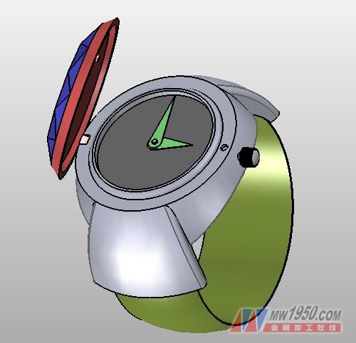
The watch is designed in the shape of a ring, which is both beautiful and practical, but the parts of the watch are numerous and complicated. Through the intelligent 3D CAD design of Zhongwang 3D, the CAD model of the ring watch can be easily completed. With the multi-object production of Zhongwang 3D, a certain component can be edited in a targeted manner. If you design CAD as a whole, when there are too many steps, you need to replay the part when editing a part, which will result in inefficient or even impossible editing of the CAD design. Zhongwang 3D's multi-object file can solve this complicated CAD design problem well, and it is reduced to zero, which makes the 3D CAD design simple and easy to manage. The following describes the specific 3D CAD design process.
First, the case part
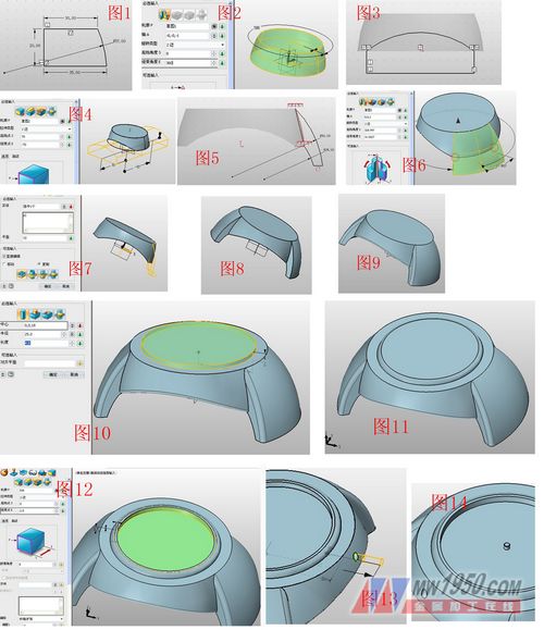
1. Create a new multi-object file named "Ring Watch". Create a new object and name it "case." Insert the sketch 1 in the XZ plane and draw the graph shown in Figure 1. Exit the sketch and rotate the sketch 1, as shown in Figure 2. Sketch 2 is drawn on the XZ plane, and the graph shown in Figure 3 is drawn. Then stretch the sketch 2 and select the subtraction operation, as shown in Figure 4. Sketch 3 on the XZ plane, as shown in Figure 5. Rotate the sketch 3, select "Base", and note that "Start Angle" and "End Angle" use the "Target Point" to select the two points of Figure 6. Need to explain here, when setting a certain parameter in Zhongwang 3D, such as "starting angle", "end angle", "axis" and other parameters, you can right-click in the drawing area to make some auxiliary selections, which can be quick and convenient. Setting parameters. Click on the image, select the shape in the "Property Filter", mirror the rotating body in the previous step, as shown in Figure 7, the effect is shown in Figure 8, and the edge is rounded, the effect is shown in Figure 9.
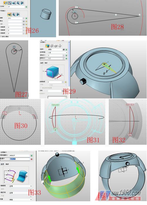
2. Select the cylinder and draw the graph shown in Figure 10 to form the boss. The parameters are as shown. Round the upper edge of the cylinder as shown in Figure 11. Select the stretch-subtraction operation, the contour is the upper surface of the boss, and pay attention to the offset-contraction/expansion. The parameters are shown in Figure 12. A circle with a radius of 1.5 is drawn on the XZ plane, and a circular hole having a depth of 2 is pulled out by the stretching-subtracting operation as a shaft hole of the crown, and the position is as shown in FIG. Using a cylinder-plus operation, the cylinder is drawn in the center of the dial with a radius of 1, a length of 1.5, and rounded corners, as shown in Figure 14.
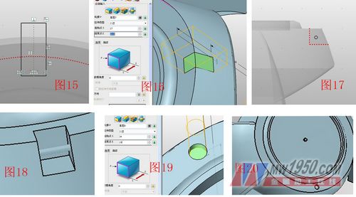
3. Sketch 4 on the XY plane, the shape is shown in Figure 15, the short side of the rectangle is 4, and the stretch-minus operation is used to stretch the sketch 4, and the groove with the depth of 4.3 is pulled out as the joint between the case and the cover. Slot, as shown in Figure 16. Insert sketch 5 on the YZ plane, draw a circle with a radius of 0.4, as shown in Figure 17, and stretch the sketch 4 as the connecting axis of the case and the cover, as shown in Figure 18. Similarly, draw a circle with a radius of 1.3 on the XY plane. The position is as shown in Fig. 19, and a circular hole having a depth of 1 is stretched, which is an insertion hole when the cover is closed, and the effect is as shown in Fig. 20. Exit the part edit and return to the multi-object file interface.
Second, the crown part
Create a new object, type is part/assembly, name it “Assemblyâ€, right click in the drawing area, select “Insert Componentâ€, select the completed “Table Caseâ€, the position is (0,0,0), OK. Right-click in the drawing area again, select Insert Component, enter "Crown" in the text box, and create a new crown part with the insertion position (0,0,0). Select the "Crest" component in the manager and select "Edit Part" in the pop-up menu to enter the part editing mode.
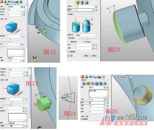
Click on the menu bar → View → Display Range → Show All to display all components. Click “Reference Curveâ€, select the circle at the bottom of the side hole of the case, and stretch the reference curve. The parameters are as shown in Figure 21. Click on the stretch again. The contour selects the round face of the cylinder shown in Figure 21 and stretches 4. Offset 2, forming a boss, as shown in Figure 22.
Select the dome tool, the boundary is the boss round face, the height is 1, and the tangency coefficient is adjusted moderately, as shown in Figure 23. Insert sketch 6 on the XZ plane, click on the reference curve, select the edge of the boss circle, draw the graph shown in Figure 24, then stretch the sketch 6, cut it with subtraction, click on the array - circle, select the attribute filter as The shape, the selected part of the base has been cut off, and other parameters are shown in Fig. 25. It is convenient to edit the cut part as a shape, and many styles can be easily realized.
Third, the hands and straps
1. Similarly, insert the component, name it "hour hand" and enter the editing state, the reference datum is offset by 20.2, insert the sketch on this datum, draw the graph shown in Figure 27, exit the sketch and stretch 0.2; insert again Set the name to "minute hand" and enter the editing state, the reference datum plane and offset 20.5, insert the sketch on this datum, follow the above steps to draw the minute hand shown in Figure 28, and stretch 0.2, the effect is shown in Figure 29.
2, insert the component, named "strap" and enter the editing state, insert the sketch 7 on the XZ plane to draw the arc shown in Figure 30, and then insert the sketches 8, 9 in the XY plane, and draw as shown in Figures 31 and 32. Graphics, pay attention to the selection of the reference curve, click the drive curve to stake out, drive the curve to select sketch 7, and select the sketches 8 and 9 in turn, pay attention to the direction of the contour (the green arrow is in the same direction), as shown in Figure 33, round the edge of the strap. Angle processing, radius is 0.2, as shown in Figure 34.
Fourth, the cover part
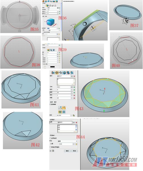
1. Insert the component, name it “Table Cover†and enter the editing state. Insert the sketch 10 on the XY plane, select the rounded edge on the surface of the reference curve, and draw a circle, as shown in Figure 35. Stretch the sketch 10 and extract the mold, the parameters are shown in Figure 36. Click the menu bar → View → Display Range → Display Target, the cover will be displayed separately, select the shell, the thickness is -2, the open surface is the lower surface of the case, as shown in Figure 37, insert the sketch 11 on the upper surface of the case, A regular hexagon as shown in Fig. 38 is drawn with a regular polygon, a reference plane XY is inserted and offset 28, and a sketch 12 is inserted on the reference plane to draw a regular hexagon, as shown in Figs.
2. Click on the wireframe-straight line and connect the two points shown in Figure 41 to form two triangles, hide the sketches 11, 12, click on the surface-N-sided surface, and patch the two triangles, as shown in Figures 41 and 42. Select Array - Circle, the base selects two triangle faces, other parameters are shown in Figure 43. The N-sided faces are again selected to repair the sides shown in FIG.
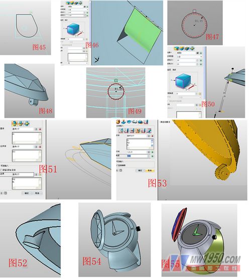
3. Click the menu bar → View → Display Range → Show All, insert the sketch 13 on the XZ surface, draw the graph shown in Figure 45, select the stretch-plus operation, and stretch the sketch 13, as shown in Figure 46, insert the sketch on the XZ plane. 14, the reference curve selects the case and the cover to connect the circular surface of the shaft, draw the circle as shown in Figure 47, select the stretch-subtraction stretch sketch 14 to form a circular hole, as shown in Figure 48, click on the reference geometry, curve selection table The circular hole on the upper surface of the shell, as shown in Fig. 49, selects the tensile-matrix, and stretches the reference curve, and the parameters are as shown in Fig. 50.
4. Select the combination-addition operation. The base and the merged body respectively select the cover and the stretched cylinder. Note that the parameters of the "boundary" select the two faces shown in the gray line of Fig. 51. The effect is shown in Fig. 52. This function is very Practical, even if stretched too much, it can be easily solved. Select the movement-rotation direction rotation, the entity selects the cover, the direction is the direction of the hole axis, the angle is 62 degrees, as shown in Figure 53, click menu bar → view → display range → display all, you can see the effect as shown in Figure 54, Edit each component in turn, and set the color of each component in the visual style-surface properties. The final result is shown in Figure 55.
At this point, the 3D CAD modeling process of the ring watch is over. Through this 3D CAD tutorial case, you can more deeply understand and apply the multi-object file function of Zhongwang 3D. Interested friends can also continue to use their imagination to create more creative CAD models of watches with Zhongwang 3D. You are also welcome to come to Zhongwang Technology Community to learn 3D CAD assembly (http://) and further make the 3D CAD model of this case into assembly animation.
Channel End Cap ,Galvanized Track Plug ,Zinc White Channel Plug,Channel End Caps
Jiaxing Gates Hardware Products Co.,Ltd , https://www.888gates.com