The wet dual clutch automatic transmission (DCT) is a new type of automatic transmission consisting mainly of oil pump, wet double clutch, electronic control system, hydraulic system and gears. The DCT consists of two input shafts, one for controlling the odd-numbered gears and the other for controlling the even-numbered gears. The electronic control system and the hydraulic system control the combination and separation of the gears. When shifting, one clutch loses power to the engaged gear while the other clutch energizes the pre-engaged gear. Through the alternating operation of the two clutches, the continuous transmission of power is achieved, which has the advantages of smooth shifting, high efficiency and good comfort.
Compared with manual transmissions, DCT power transmission components include not only intermeshing gear pairs, but also components such as oil pumps, valve bodies and dual clutches. These components generate a large amount of heat due to power loss during operation, which makes the temperature of the DCT lubricating oil rise, and the DCT lubricating oil is prone to aging due to long-term work at high temperatures. Aging DCT lubricants can cause ablation of the double clutch and synchronizer friction plates, gear pitting, gluing, and aging of rubber seals, reducing the life of the DCT. Therefore, DCT requires a cooling system to control the temperature of the DCT lubricant to a reasonable range, increasing the life of the lubricant and DCT.
DCT cooling system design
1.DCT cooling system type
The role of the DCT cooling system is to ensure that the DCT lubricant operates within the normal temperature range. At present, the cooling systems commonly used in automatic transmissions are air-cooled and water-cooled. The air-cooled cooling system uses the air around the vehicle to flow through the transmission cooler to directly dissipate the heat of the lubricating oil into the atmosphere, but is greatly affected by the wind speed. When the vehicle is continuously shifting or climbing at low speed, The cooling effect is not obvious due to the small wind speed. In addition, when the transmission is just started in winter, the transmission oil temperature rises slowly, which is not conducive to the operation of the transmission just after starting. The water-cooled cooling system uses the cooling water of the engine to exchange heat with the lubricating oil of the automatic transmission, and the heat of the automatic transmission lubricating oil is dissipated by the cooling water of the engine, and the automatic transmission lubricating oil can be utilized by the engine cooling water during the winter start. heating.
Considering the advantages and disadvantages of air-cooled cooling system and water-cooled cooling system, as well as the working characteristics of DCT and the layout environment of the vehicle, this paper designs a water-cooled cooling system for DCT. The cooler is monolithic and consists of cooling fins, mounting plates and pipe joints. The cooler is cooled by heat exchange between the cooling water and the lubricating oil, and the cooling fins increase the heat dissipation area of ​​the water and the lubricating oil. In the cooler, the cooling water and the lubricating oil are separated from each other by a separate flow, a water passage, and an oil passage, so that the contact area between the water flow and the oil flow is larger. In addition, the DCT cooling system is designed to keep the flow direction of the cooling water opposite to the flow direction of the lubricating oil, and the counterflow design ensures better cooling.
2.DCT cooling system circulating waterway
The engine's cooling water cycle includes large cycles and small cycles. The large cycle is characterized by a large amount of cooling water, and the cooling circulating water passes through the radiator, and the water temperature is relatively low after being radiated through the radiator, but the cooling water circulation is only when the water temperature of the cooling water is higher than the temperature of the thermostat opening. . The small cycle is characterized by a relatively small amount of cooling water and a relatively high water temperature, but the cooling water circulates as long as the engine is in operation. In order to ensure that cooling water flows through the cooler in the DCT cooling system at all times, heat exchange with the oil circuit of the DCT is performed, and cooling water is connected from the small cycle of the engine to the cooler. The pump displacement characteristics of an engine are shown in Figure 1. When the engine speed is 5000r/min, the displacement of the pump reaches 90L/min. According to the design of the engine waterway, the flow to the DCT cooler and the air conditioner heater is about 24%. That is 21.6 L/min. The DCT cooler is connected to the cooling cycle of the engine by means of a DCT cooler in parallel with the heater, and the heat exchange is realized by the water circulation of the engine and the lubricating oil of the DCT. The cooling water circulation route is shown in Figure 2.
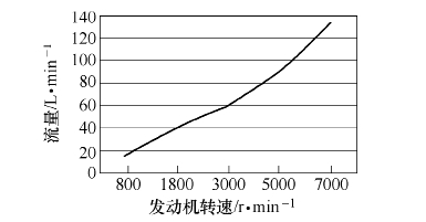
Figure 1 Pump flow characteristics
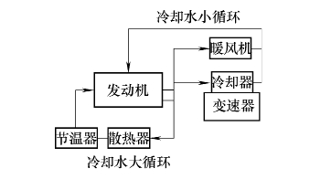
Figure 2 DCT cooling system circulating waterway
3.DCT cooling system circulation oil circuit
The purpose of the DCT cooling system is to take away the heat from the dual clutch automatic transmission lubricant with cooling water.
The heat balance formula is:
Q=C×q×ΔT
Where Q—lubricating oil absorbs/dissipates heat (W);
C——specific heat of lubricating oil (J/(kg·K));
Q——mass flow rate of lubricating oil (kg/s);
ΔT——Lubricating oil temperature difference (°C).
According to the heat balance formula, it is known that increasing the flow rate of the DCT lubricating oil through the cooler can achieve better cooling effect, but at the same time, the demand of the dual clutch for the amount of lubricating oil and the influence of the pressure drop of the cooler on the oil passage are considered. The oil circuit cycle of the designed DCT cooling system is shown in Figure 3. The oil circuit system of the DCT cooling system mainly includes an oil pump, a safety valve, a pressure regulating valve, a cooler, etc., in which a, b, c, d, e, f, g are throttle ports.
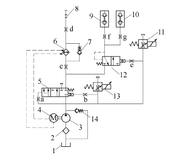
Figure 3 DCT cooling system circulation oil circuit
1. Fuel tank 2. Filter 3. Oil pump 4. Engine 5. Pressure regulating slide valve 6. Heat exchanger
7. Bypass valve 8. Shaft teeth 9, 10. Clutch C1, C2 11, 13. Proportional solenoid valve
12. Lubrication cooling slide valve 14. Safety valve
The pressure regulation system in the DCT cooling system oil circuit regulates the pressure of the DCT and controls the pressure through a spool valve and solenoid valve. The principle of pressure regulation utilizes the spool balance of the spool, ie the forces acting on the ends of the spool are equal. The force acting at one end of the pressure regulating slide valve is the pilot pressure and spring force generated by the variable flow proportional solenoid valve to control the oil pressure, and the other end force is the main pressure of the cooling system. The solenoid valve is a variable flow proportional solenoid valve. The current value is adjusted by an electronic control system. The magnitude of the current determines the amount of leakage of the solenoid valve. The amount of pilot pressure acting on the end of the pressure regulating spool is adjusted by the change of the leakage amount. The main pressure of the cooling system changes as the pilot pressure changes. At the same time, the main pressure is different, the position of the pressure regulating spool is different, which affects the flow to the cooler and the clutch lubrication cooling.
The cooler oil circuit and the lubrication cooling oil circuit are designed in a parallel mode. Since the dual clutch does not slip, the required cooling flow is small, and designing the cooler on the dual clutch lubricating oil circuit will affect the cooling performance of the cooler. A throttle port c is designed on the oil circuit of the cooler for controlling the flow to the cooler, and when the oil pump is rotating at a low speed, the flow demand for clutch lubrication is also ensured. In the case where the pressure drop of the lubricating oil does not change, the larger the area of ​​the orifice, the larger the flow rate to the cooler. A lubrication and cooling adjustment system is designed on the dual clutch lubrication cooling oil circuit. The electronic control system controls the current acting on the solenoid valve to realize the dual clutch lubrication flow demand under different working conditions.
Test verification
To verify the effectiveness of the designed DCT cooling system, a thermal balance test was performed on the entire vehicle loaded with this DCT cooling system. The test ambient temperature is 40 °C, the light intensity is 950W/m2, the vehicle is fully loaded, and the maximum opening degree of the air conditioner is cycled. The whole vehicle loaded with DCT is tested at idle speed, high speed (vehicle speed 130km/h), climbing (slope 12%). The oil temperature of the transmission under working conditions. When the test is carried out at three operating conditions, the test is terminated when the oil temperature and the water temperature reach equilibrium, that is, the water temperature difference and the oil temperature difference are both less than 5 ° C / min.
Figure 4 shows the heat balance curve of the DCT cooling system at idle speed. When the heat balance is reached, the oil inlet temperature of the cooler is 92.4 ° C, the oil discharge temperature is 92.5 ° C; the inlet temperature of the cooler is 92.75 ° C, and the outlet water temperature is 91.875 ° C. From the trend of the curve in Figure 4 and the temperature of the inlet and outlet of the cooler and the inlet and outlet temperatures of the cooler, the temperature of the inlet and outlet of the cooler and the temperature of the inlet and outlet water are basically unchanged. The water does not cool, but it has a slight heating effect on the lubricating oil. The overall working temperature of the lubricating oil is about 92.5 °C.
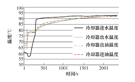
Figure 4 DCT cooling system temperature during idle conditions
Figure 5 shows the thermal balance curve of the DCT cooling system at high speeds (vehicle speed 130km/h). After the heat balance is reached, the inlet temperature of the cooler is 106.8 ° C, the outlet temperature is 112.75 ° C; the inlet temperature of the cooler is 125.1 ° C, and the outlet temperature is 115.1 ° C. As can be seen from Fig. 5, at the beginning of the high speed operation, the inlet temperature of the cooler is higher than the inlet temperature of the cooler, at which time the engine cooling water heats the DCT lubricating oil, after the initial stage, The inlet temperature of the cooler and the inlet temperature of the cooler continue to rise. At this time, the cooling water temperature of the engine is lower than the temperature of the DCT lubricating oil. The engine cooling water starts to cool the DCT lubricating oil, and the temperature of the DCT lubricating oil drops after cooling. Around 10 °C.
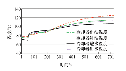
Figure 5 DCT cooling system temperature during high speed operation
Figure 6 shows the thermal equilibrium curve of the DCT cooling system for climbing conditions (12% slope). After the heat balance is reached, the inlet temperature of the cooler is 115.2 ° C, the outlet temperature is 117.25 ° C; the inlet temperature of the cooler is 117.3 ° C, and the outlet temperature is 115.2 ° C. According to the curve analysis of the heat balance, the engine cooling water cools the lubricating oil after the heat balance is reached, and the temperature of the DCT lubricating oil can be lowered, but the cooling effect is not obvious when the speed is high.
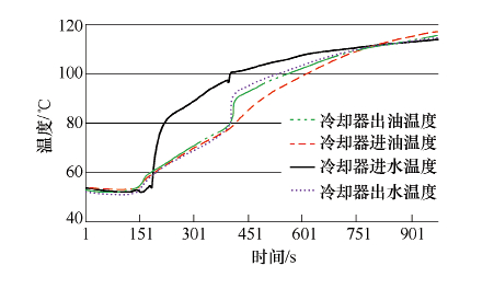
Figure 6 DCT cooling system temperature during climbing conditions
Conclusion
Because the DCT contains energy-consuming components such as oil pump, valve body, double clutch, gear, etc., the heat generation of DCT is relatively high. To ensure the service life of DCT lubricating oil, our institute has designed a circuit cooling system for DCT. The designed cooling system is applied to the whole vehicle for heat balance test, and the heat balance test is carried out by selecting three working conditions of idle speed, high speed and climbing. The test results show that the DCT cooling system cools the lubricating oil, especially at high speeds. When the idle temperature is not high, the DCT cooling system does not cool, and the lubricating oil works at a suitable oil temperature. .
Industrial Sectional Door
Industrial sectional doors are the most durable and longest lasting doors to ensure circulation at the areas of the factory entrance and exit of goods, loading and unloading areas.
The body of sectional door is forming by 40 mm sandwich panels. These panels provides sound and heat insulation due to the intense doped polyurethane insulation was injected between galvanized steel sheet. (50 kg/m3).
Industrial sectional door systems provide space-saving with opening parallel to the ceiling.Any opening can be used clearly . and produces in accordance with the transition range and the height in the factory buildings or warehouses.
Doors is working sliding by be the most appropriate the gap between the top level of the gate with a ceiling height within the side rasils. The door can be mounted in different ways according to the gap distance (standard, low, highlift and vertical track systems).
Industrial sectional doors can easily be opened automaticly by 230-380 V-AC/50 Hz electric motor or manualy thanks to torsion spring system that balances the weight of the door.The galvanized springs are made to be durable of 25.000 door cycles.Motor with emergency chain All the drive systems have a mechanical back-up system fitted to the reduction gearbox of the electric motor, so that the sectional door can be opened if the power fails. The reduction gearbox can then be powered using the chain.
Industrial Sectional Door,Industrial Overhead Sectional Door,Industrial Warehouse Sectional Door,Industrial Garage Interior Sectional Door
Shenzhen Hongfa Automatic Door Co., Ltd. , https://www.hfrollershutterdoor.com


