Design of 5kW Photovoltaic Maximum Power Point Tracking Circuit
1 Introduction
The residential networked photovoltaic system has low investment, quick effect, energy saving and environmental protection, and is very suitable for the development of buildings with plenty of buildings and sunshine. In order to improve solar energy utilization, photovoltaic power generation operations generally use maximum power point tracking control (MPPT). Maximum power point tracking is an important key technology in solar grid-connected power generation. It refers to the method of controlling the output voltage or current of the solar array to make full use of solar energy, so that the array always works at the maximum power point. According to the characteristics of solar cells, there are three main tracking methods: sun tracking, maximum power point tracking or a combination of two methods. For economic reasons, the method of maximum power point tracking is often used in small-scale systems.
2 Solar maximum power point tracking circuit and its parameter determination
In this paper, a two-stage transformerless photovoltaic grid-connected topology is adopted. The pre-stage DC-DC link realizes MPPT, and the latter-level H-bridge link realizes grid connection. The pre-stage DC-DC boosting section can adopt various forms of topology, and the maximum power tracking can be realized by adjusting the duty ratio of the DC-DC converter. From the perspective of converter efficiency, the BUCK and BOOST circuits are the most efficient in various topologies, the BUCK-BOOST circuit is second, the half-bridge and the full-bridge are again, and efficiency is very important for the application of photovoltaic systems. The BOOST circuit is also ideal for maximum power tracking in grid-connected systems. First, it makes the voltage configuration on the DC side more flexible. The BOOST circuit is a boost converter, so that the maximum power point voltage of the PV array can be lower than the peak voltage of the AC side, and then the inverter is boosted by the BOOST circuit; The BOOST circuit itself has high efficiency, and the diode can be used as a natural source to prevent the energy on the grid side from being applied to the photovoltaic array; again, the energy is decoupled at the output of the BOOST circuit, so that the input end of the BOOST circuit, that is The output of the photovoltaic array can be controlled by means of small fluctuations, so that the accuracy of the maximum power tracking is improved. Therefore, the DC-DC link of the front stage of the system adopts the BOOST boost circuit structure. The BOOST circuit structure adopted in this paper is shown in Figure 1.
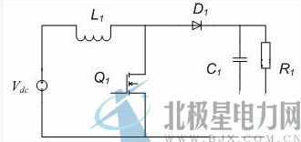
Figure 1 BOOST circuit topology
2.1 BOOST inductance design
The BOOST circuit used in this paper works in continuous conduction mode, and it can be obtained according to the principle of volt-second product balance in steady state.
Vpv*DTs+(Vpv-Vdc)*(1-DTs)=0; (1)
In the formula:
Vpv - photovoltaic array output voltage;
Vdc - BOOST output circuit;
DTS - the on-time of the switch.
After finishing, you can get: Vdc/Vpv=1/(1-D) (2)
Assume that the circuit has no loss, that is, the input and output power are equal.
Ir/Il=1-D (3)
In the formula:
Ir - the average current of the load;
Il - The average current of the photocell input is the inductor current.
Obtained by V1=L*di/dt
â–³Il=Vpv*DTs/L (4)
In the formula:
△Il——inductor ripple current;
L——Input inductance value.
Define ηi=ΔIl/Il, which is available from the above:
L=(1-D) 2 *D*Vdc 2 *Ts/ηi*Pr (5)
Where: Pr - BOOST circuit output power.
When other conditions are constant, when D=1/3, L takes the maximum value.
Lmax=4Vdc 2 *Ts/27*ηi*Pt (6)
In this system, the input voltage range of the photocell is Vpv=200V~550V, the current ripple is ηi≤25%, the input power is Ppv=5500W, the output bus voltage is Vdc=350V, and the switching tube frequency is 16kHz. According to the formula (6), Lmax=825 μH can be obtained, and Lmax=900 μH is taken herein.
2.2 Bus capacitance design
For the continuous conduction mode, it is assumed that all ripple current components flowing through the diode current flow through the capacitor, and the average value flows through the load resistor. Assuming that the H-bridge inverter can be equivalent to a resistive load, the bus voltage is stabilized at 350V. From equations (2), (3) and I=C*dV""/dt:
â–³Vdc=Pr*DTs/Cdc (7)
In the formula:
△Vdc——capacitor voltage ripple;
Cdc - bus capacitance value.
Define ηv=△Vdc/Vdc as the voltage ripple factor, then
Cdc≥Pr*DTs/ηv*Vdc 2 (8)
The pharmacist bus voltage satisfies Vdc=350V±1%, Vdc=350V, D=0~0.4286, ηv=1%, Pr=5500W, Ts=62.5us, which can be obtained by formula (8):
Cdc≥5500*0.4286*62.5*10 -5 /0.01*350 2 =120(uf)
In the actual circuit, the bus capacitor has the function of energy storage in addition to the output filter, and the H-bridge inverter can not be completely regarded as a pure resistive load, so the intermediate capacitor takes 20 times larger margin, with 2500μF capacitance. Five 300V, 1000μF capacitors are connected in series in the circuit and then connected in parallel with the same set of capacitors.
2.3 Switch tube design
Due to the advantages of MOSFET in low voltage and high frequency, MOS tube is selected as the switching tube of Boost circuit. In the circuit, the maximum voltage of the MOS tube is 600V and the current is 28A. Therefore, an Infineon SPW47N60C3 MOS tube is selected. The main parameters of SPW47N60C3 are: withstand voltage of 650V and rated current of 47A.
2.4 Diode design
The diode in the boost chopper circuit should have a low on-state voltage drop and fast reverse recovery characteristics. It can withstand a maximum voltage of 600V and a current of up to 28A in the circuit. Therefore, the main parameters of the diode are: withstand voltage of 600V. The current is 40A.
3 MPPT control implementation method
At present, the most commonly used MPPT control methods are power disturbance method and conductance increment method. Combined with the actual situation of the project, this paper applies power disturbance method to realize MPPT. The principle of the disturbance observation method is to first give a disturbance output voltage signal (VPV+ΔV) and then measure its power change. Compared with the power value before the disturbance, if the power value increases, it indicates that the disturbance direction is correct and can continue to the same. (ΔV) direction disturbance; if the power value after the disturbance is less than before the disturbance, it will be disturbed in the opposite (ΔV) direction. The biggest advantage of this method is that the structure is simple, the measurement parameters are small, and the output power of the array is maximized by continuous disturbance. Control flow chart shown in Figure 2
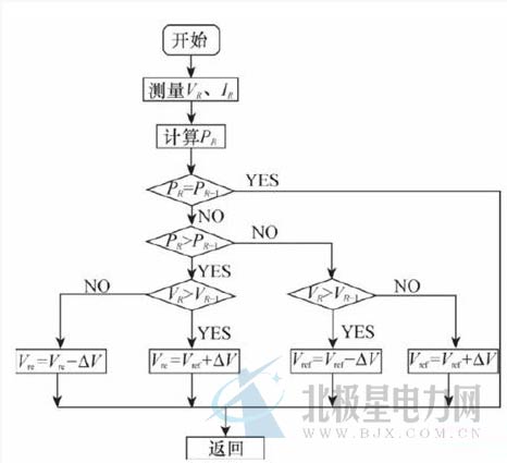
Figure 2 MPPT flow chart
The system control block diagram of the MPPT function implemented by the entire BOOST circuit is shown in Figure 3.
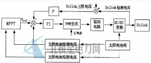
Figure 3 system control block diagram
According to the above design parameters and control methods, a 5kW simulation platform was built, as shown in Figure 4.
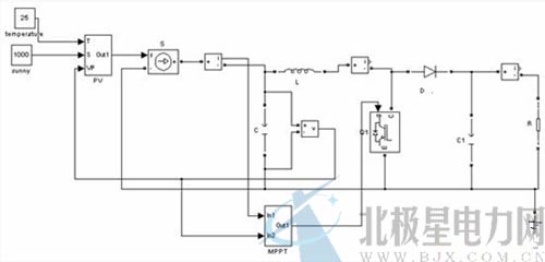
Figure 4 system simulation diagram
In the figure, PV is a photovoltaic model, T is the operating temperature of the solar panel, S is the solar illumination intensity, VP is the photovoltaic cell operating voltage, and MPPT is the system control core module. Completed all parts of Dclink in the system control block diagram of Figure 3; including MPPT calculations, PI calculations, PWM generation, and drive signal generation.
4.1 Simulation analysis of changes in light intensity
When the initial battery temperature T is 25°, the solar light intensity S is 800 W/m2, the light intensity rises to 1000 W/m2 at 0.1 S, rises to 1200 W/m2 at 0.15 S, and drops to 800 W/m2 at 0.2 S, 0.25. When S, it rises to 1000W/m2. When the temperature remains unchanged, the maximum power tracking is shown in Figure 5. In the figure, blue is the maximum power and green is the tracking power. As can be seen from the figure, as the light intensity changes, the maximum power point changes.
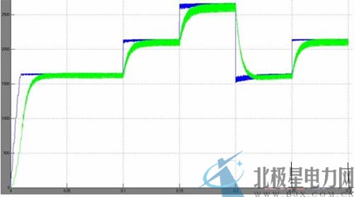
Figure 5 Maximum power tracking diagram when the light intensity changes
4.2 Simulation analysis of battery temperature change
When the initial light intensity is maintained at 1000W/m2, the photocell temperature is 25°. When the photocell temperature rises to 35° at 0.15S and the photocell temperature rises to 45° at 0.2S, the light intensity remains unchanged. The maximum power tracking is as shown in the figure. As shown in Fig. 6, blue is the maximum power and green is the tracking power. It can be seen from the figure that as the temperature changes, the maximum power point changes.
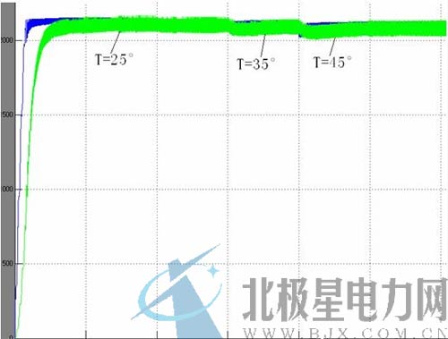
Figure 6 Maximum power tracking diagram when temperature changes
It can be seen from Fig. 5 and Fig. 6 that under the disturbance of temperature and illumination, the maximum output power point of the photocell is changing, and the maximum power point tracking can be achieved well by the design scheme of this paper.
5 Conclusion
Taking 5kW/220V solar MPPT control as an example, this paper introduces the control circuit and system block diagram of maximum power tracking, and clarifies the parameters determination method of each component of DC-DC boost chopper circuit. The design of MPPT is based on the power perturbation method. The self-optimization algorithm is used to track the maximum power point. The solar MPPT control system is simulated by MATLAB software to verify the rationality and feasibility of the scheme.
references
[1] Li Jing, Dou Wei, Xu Zhengguo, et al. Research on Maximum Power Point Tracking Algorithm in Photovoltaic Power Generation System[J]. Journal of Solar Energy, 2007(3).
[2] Zhang Ling. Development of single-phase photovoltaic grid-connected inverter. Master's thesis of Beijing Jiaotong University, 2007.
[3] Lin Fei, Du Xin, ed. MATLAB simulation of power electronics application technology [M]. Beijing: China Electric Power Press, 2009:1
Cut-Off Wheels is a simplified product of thousands of impeller, mainly used in industrial production of polishing, is also a kind of industrial consumables products. The impeller matrix has mesh cloth, nylon, plastic, steel paper, etc., the number of pages varies, and is evenly distributed in fan shape. Particle size 36#-400#, 60#, 80# is the most common, the outer diameter of 4"-7" installed in the angular grinder, used for welding seam, positive edge burr grinding and grinding processing, can be interchangeable with the cymbal grinding wheel, has the advantages of good elasticity, high efficiency, good heat loss, low noise can replace the resin cymbal grinding wheel, it has strong elasticity, high tensile and bending strength, Good self-sharpening, high grinding rate, low noise, suitable for grinding the welding seam in the box and the flash edge of the stamping parts. It is mainly used for grinding and polishing of various stainless steel and carbon steel structural parts.
Cut-Off Wheels,Grinding Wheel,Disc For Angle Grinde,Flap Wheel
Behappy Crafts (suzhou)Co.,Ltd , https://www.haoyuebehappy.com