During operation, under the action of the cam and the plunger spring on the camshaft of the fuel injection pump, the plunger is forced to reciprocate up and down to complete the pumping task, and the pumping process can be divided into the following three stages.
Oil feeding process
When the convex portion of the cam is turned over, the plunger moves downward under the action of the spring force, and the upper space of the plunger (called the pump oil chamber) generates a vacuum degree, and when the upper end surface of the plunger puts the plunger into the sleeve After the oil hole is opened, the diesel oil filled in the oil passage of the oil pump enters the pump oil chamber through the oil hole, and the plunger moves to the bottom dead center, and the oil feed ends.
Oil supply process
When the camshaft turns to the convex portion of the cam to lift the roller body, the plunger spring is compressed, the plunger moves upward, the fuel is pressurized, and a part of the fuel flows back through the oil hole to the body oil chamber of the fuel injection pump. When the top surface of the plunger covers the upper edge of the oil inlet hole of the sleeve, the pumping chamber at the top of the plunger becomes a sealing oil chamber due to the small clearance of the plunger and the sleeve (0.0015-0.0025 mm). Continue to rise, the oil pressure in the pump oil chamber rises rapidly, the pump oil pressure> the oil valve spring force + the high pressure oil pipe residual pressure, push the oil valve out, the high pressure diesel oil enters the high pressure oil pipe through the oil discharge valve, sprays through the fuel injector Into the combustion chamber.
Oil return process
The plunger is supplied upwardly, and when the chute (stop supply side) which is ascended to the plunger communicates with the oil return hole on the sleeve, the low pressure oil passage of the pump oil chamber and the middle hole and the radial hole of the plunger head With the chute communication, the oil pressure suddenly drops, and the oil discharge valve is quickly closed under the action of the spring force to stop the oil supply. After that, the plunger is still going up. When the convex portion of the cam is turned over, the plunger is further lowered by the action of the spring. The next cycle begins.
Conclusion: Through the above discussion, the following conclusions are drawn
1 The total stroke L of the plunger reciprocating motion is constant and is determined by the lift of the cam.
2 The amount of oil supplied per cycle of the plunger depends on the oil supply stroke, and the oil supply stroke is variable regardless of the camshaft control.
3 The fuel supply start timing does not change with the change of the oil supply stroke.
4 Turn the plunger to change the end of the oil supply and change the oil supply.
3. Domestic series plunger type fuel injection pump
Domestic series of piston pumps mainly include A, B, P, Z and I, II, III and other series. The serialization is based on the requirements of the single-cylinder power range of the diesel engine. It is based on the plunger stroke, the center distance of the pump cylinder and the structure type, and is respectively equipped with plunger diameters of different sizes to form several kinds in one working cycle. Fuel injection pumps with different internal fuel supply to meet the needs of various diesel engines.
The working principle and structure type of the domestic series of fuel injection pumps are basically the same. The structure and working principle of the plunger type fuel injection pump are introduced by taking the A type pump as an example. The plunger pump consists of four parts: the sub-pump, the oil quantity adjustment mechanism, the transmission mechanism and the pump body.
The latest domestic intelligent piston pump is intelligent control of the microprocessor, LCD display, and can communicate with the computer. It has the characteristics of stable working pressure, small pulsation and convenient operation. It is widely used in biochemical, pharmaceutical, chemical, environmental protection and other industries to meet the requirements of continuous constant pressure and constant flow of liquids in the above industries.
Steel belt elevator advantages
1. Steel belt traction elevator, can maximize the utilization rate of well, reduce the top height, reduce pit depth.
2. Maintenance-free: the inner steel belt is multi-strand high strength steel wire, the surface is polyurethane polymer material, without lubrication.
3. High life: the life of steel belt is 2â€3 times that of traditional steel wire rope.
4. High efficiency: the steel belt and wheel contact area is larger, more efficient and energy saving.
5. Noise reduction: steel belt and wheel friction noise is less.
6. Because the diameter of the main wheel and the regulating wheel of the steel belt becomes smaller, there is no need for Angle change, which is beneficial to prolong the life of the steel belt and smooth operation.
Notes for installation of steel belt elevator
1. High levelness is required for the steel belt host due to the larger width of the traction wheel.
2. At the same time, ensure the levelness of the main wheel and the regulating wheel in all directions to prevent the deviation of the steel belt.
3, keep the cleanliness of the steel belt.
4, FAXI steel belt host specially equipped with McGowdy steel belt, pay attention to the rough surface of the steel belt and traction wheel contact when installing.
5. Confirm the consistency of the tension force of each steel belt
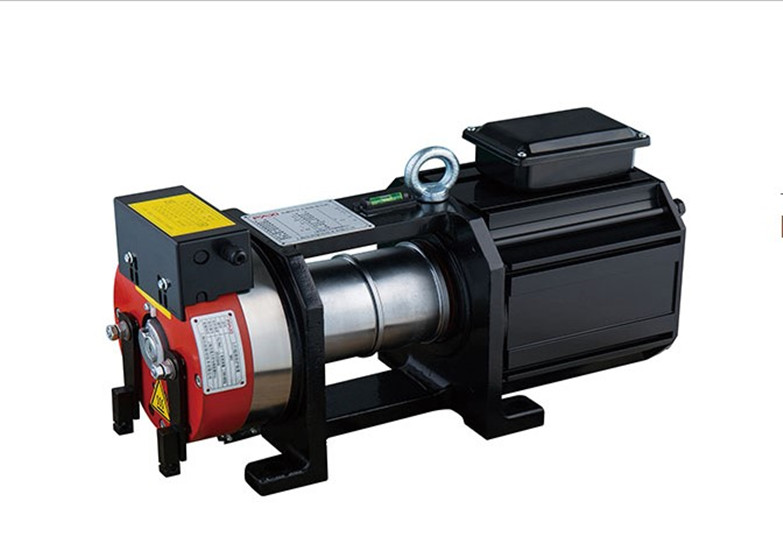
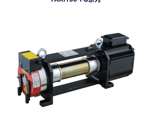
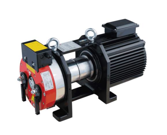
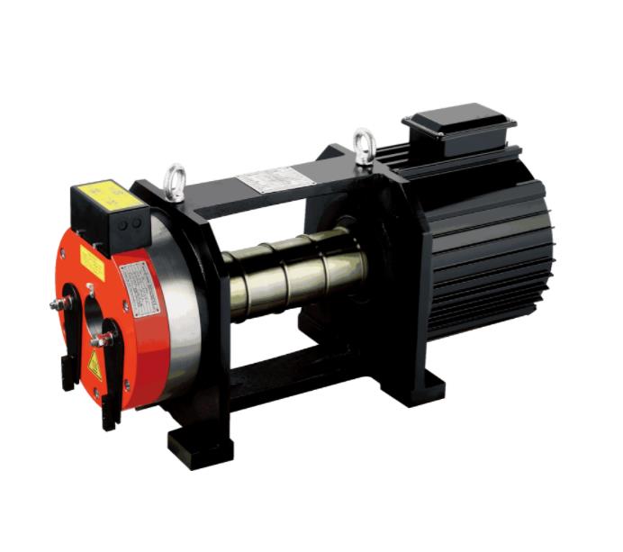
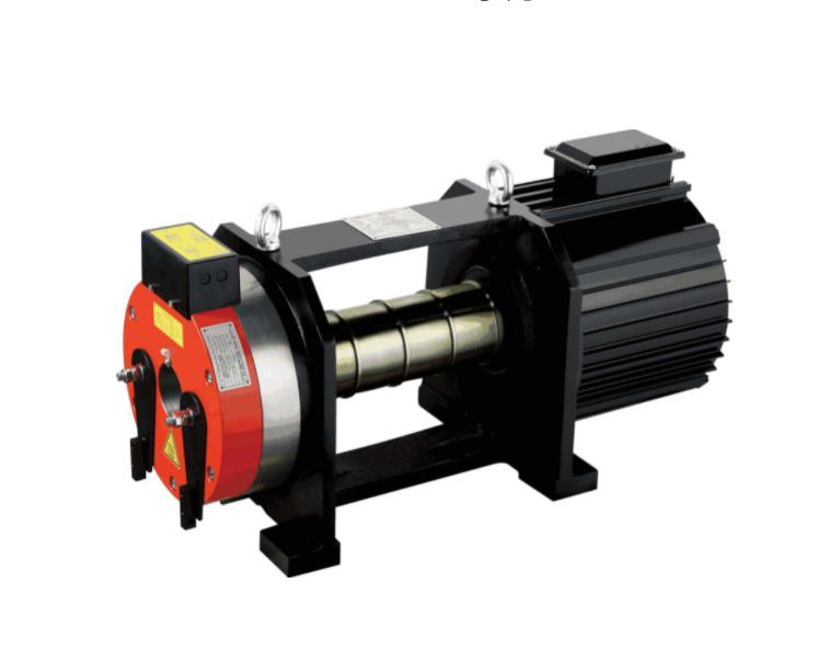
Belt traction machine,Steel belt traction machine,gearless traction machine,Belt motor,gearless motor
Suzhou Keffran Parts Co.,ltd , https://www.keffran-elevatorsmart.com